It’s a sad, familiar story: a game programmer wants to create a 3D game, but has no 3D models to use!
If this sob story sounds familiar, don’t feel bad — you’re not alone. In this situation, you have four options:
- cry
- find free 3D models online
- pay an artist to make some
- create your own — it’s not as hard as you think!
If you’ve never touched Blender before but want to be able to make some simple objects for use in your game, look no farther – this tutorial is for you!
In this Blender tutorial for beginners, you’ll learn the basic setup of Blender by creating a cute creature you will undoubtedly recognize from the 8-bit days. :] This tutorial won’t cover everything Blender can do, just the stuff you need to know to get started making objects and using them in games!
This tutorial covers the following concepts:
- Blender basic setup
- Adding and transforming objects in Object Mode
- Editing the object in Edit Mode
- Unwrapping the object’s UV mesh
- Creating a texture
- Exporting your files.
Getting Started
Note: If you don’t have Blender installed on your computer, download a copy here. Like other 3D modeling tools, Blender is a graphically intensive application; if you’re planning to install Blender on an older computer, check out the system requirements before installing to make sure your rig will run Blender without a lot of frustrating lag.
Once you have Blender installed, launch it and you’ll be greeted by a splash screen. Click anywhere outside of the splash screen to get started. You should see the default scene that contains a cube, a camera and a lamp, as illustrated in the screenshot below:

Note: Don’t see the elements above? Simply select File > New to generate a new scene with the requisite starter objects.
These objects are located in the 3D view that has X, Y, and Z axes. These axes help position and edit your objects in 3D space.
To help tell them apart, the X-axis is red, the Y-axis is blue, and the Z-axis is green. The grid you see on the screen represents the XY plane, and the Z axis extends perpendicular to the XY plane. You can always confirm the orientation of your view by checking the mini axis in the bottom left-hand corner of the 3D view.
There are four panes on the screen that you’ll use to create your 3D objects:
- Outliner: lists all objects in your scene.
- Properties: allows you to edit the properties of whatever object or material you are working with.
- 3D View: contains all the objects you’re creating. Note the toolbar at the bottom, you’ll be using this quite a bit later on.
- Tool Shelf: displays any relevant options for the action you’re currently performing in Blender.
The following screenshot shows the relative positions of the four panes noted above:

Now that you’ve received the five-cent tour of the app, it’s time to cover a few concepts that you’ll need before creating your first 3D model.
Controlling Your View
Navigating around your 3D view is something you’ll be doing frequently, so you should get really comfortable with the navigational controls. The primary ways to manipulate your view are as follows:
- To rotate your view: hold the middle mouse button and drag around.
- To zoom your view: use the mouse scroll wheel
- To pan up and down: hold down Shift and use the mouse scroll wheel
- To pan right and left: hold down Control and use the mouse scroll wheel
There are two views for your 3D scene: orthographic, which means your object is drawn linearly without any perspective distortion, and perspective, which means that objects further away in your view appear smaller, and lines on your objects display perspective distortion.
The difference between these two views is illustrated below:

Although perspective view looks more natural, you’ll probably find it easier to design your objects using the orthographic view where you can view and edit objects on a flat plane. The images below show the benefit of designing in the orthographic view:

The default view for a new scene is the perspective view. To switch between orthographic and perspective views, select View > View Pers/Ortho (from the toolbar under the 3D View); alternatively, press 5 on the numpad. To choose a specific pre-defined view, rather than rotating around with the center mouse button, choose the view from the View menu, as shown below:


Note: Blender has earned some notoriety throughout the years due to its difficult user interface. Thankfully, Blender developers have been listening to the community and have made many usability improvements, and there are efforts to make even more. However, there are still a few things to watch out for when using Blender.
For example, as you may have noticed in the previous screenshot, the View menu is not accessible from the standard application toolbar; rather, it’s accessed from a Blender generated toolbar. The same is true for all other Blender-related functions.
Modeling Windows:
To resize the various toolbar panels, simply mouse over the edge of the panel and resize it to suit as shown below:

If you move the panel a little too far and — whoops — it disappears, click and drag the little transparent plus icon tab to pull the panel back out, as shown below (note that if you do this while the panel is visible it will create a secondary panel):

Sometimes you’ll want to have two views of your object open at the same time. To create another view window, click and drag the triangle at the top right or bottom left of the current window, as shown below:

To get rid of a view window, click and drag the top right triangle of the window you want to keep onto the window you want to remove. The window to be removed darkens; release the mouse and the second window disappears, as demonstrated in the following screenshot:

Manipulating Objects in Object Mode:
Blender works in several different modes. At this point in the tutorial, you’re in Object mode (which you can see in the toolbar below the 3D view), where you can add, delete, move, scale, and rotate your object. A little later on, you’ll move on to Edit mode — but for now you’ve got some work to do in Object mode.
Selecting Objects
Note that the cube in your scene should have a yellow outline; this means that the cube is selected. There are a few ways to select and deselect objects in Blender:
- To select an object: click it with the right mouse button.
- To deselect an object: shift-click it with the right mouse button.
- To toggle selecting all objects or no objects: press the A key.
Deleting Objects
You’re here to design a mushroom, not a sugar cube, so you’ll need to get rid of the cube from your scene. If the cube isn’t selected, click the cube with the right mouse button, press the X key, and choose Delete.

3D Cursor
So your scene has been cleared, and you’re ready to add some new shapes to your scene. But how do you know where to add them?
The 3D cursor shows you where new objects will be added, as shown below:

To set the position of the 3D cursor in your scene, click on your scene with the left mouse button.
In the scene above, the 3D cursor is not set to the center of your scene; it’s down and off to the left somewhere. You’ll need to draw your object centered in the view, so you’ll need to move the 3D cursor back to the origin. You could try to click on the origin with the mouse, but there’s an easier way.
To reset your 3D cursor to the origin, choose Object > Snap > Cursor to Center; if you’re a fan of keyboard shortcuts, hit Shift + S > Cursor to Center.
Adding Objects
Now that your 3D cursor is at the origin, press Shift-A to display the “Add” menu. Select Mesh, and you’ll be presented with all types of shapes that you can add.
Select the Cylinder shape, as shown below:

Now that you have a cylinder in your scene, check the left-hand panel to see which options are available to edit your shape. These only appear immediately after you add the object and before you’ve done any other editing, so now’s your chance to get the settings right!
Modify the following properties in the left-hand panel as follows:
- Vertices: 10
- Radius: 1.5
- Depth: 3
- Cap Fill Type: Triangle Fan
Leave all other properties as-is. Your panel should appear as below:

You can either click the field and type in the values, or you can scrub back and forth with the mouse to set the values.
Transforming Objects in Object Mode:
In Object Mode, you can transform the entire object by moving, scaling, or rotating it. There are three ways to transform objects: using the shortcut key, using the transform handles, and using the transform panel.
Transforming with Shortcut Keys
To use the shortcut keys to transform the object, first ensure the object is selected. Next, press the appropriate key to begin the action, and then move the mouse to start the transform. The further you move the mouse, the greater the magnitude of the translation.
The shortcut keys for transforms are as follows:
- Move: G
- Scale: S
- Rotate: R
For example, to scale an object, first select it, then press the S key and move the mouse to control the scaling of the transform, as shown below:

You can constrain transforms to a particular axis by pressing X, Y, or Z. Therefore if you only want to scale along the Z axis, press S (then release) and then press Z (then release). You can only constrain to one axis at a time.
To accept the changes, click the left mouse button; to discard the changes, click the right mouse button. If you’ve accepted the changes, but then change your mind, Blender provides the good old Command-Z keystroke to undo your last action.
Transforming with the X,Y,Z Handles
The second method to transform your object gives you a little more control by using the blue, green and red arrows that show up when you select an object. Your current selection should be the Translate manipulator, as shown in the screenshot below:

Click the blue arrow on your object with the left mouse button, and drag up with your mouse. You should see the object translate along the Z-axis. Undo this change by pressing Command-Z.
Next, click the Scale manipulator icon. Click the red arrow on your object with the left mouse button, and drag it around. Note that your object only scales along the X-axis. Undo this change as well with Command-Z. The Rotate manipulator works the same way.
Transforming with the Properties Panel
The third method of transforming — editing the object properties directly — offers the most control; you can use this method if you need very specific control over the shape and size of your object.
To edit the properties of your object directly, go to the Properties panel on the right-hand side of the screen and click the Object icon. This brings up all the properties of the object; you can transform the object by changing its properties in the Location, Rotation, and Scale tables, as shown below:

A note about measuring distance in Blender: distance in a 3D space is entirely relative. Blender measures distance by using Blender Units which corresponds to one grid space in the 3D viewport.
If you’re a stickler for traditional measurements, you have the option of switching to Metric or Imperial measurements. Simply select the scene icon in the properties panel, then select your desired measurement system as shown below:

For the purposes of this tutorial, any instructions involving measurements are given in Blender Units.
That covers most of what you can do in Object Mode. Now it’s time to edit the vertices, edges, and planes of the object — you’ll do that in Edit mode.
Editing Objects in Edit Mode
To enter Edit mode, select the object to be edited and press Tab.
You’ll see that the object turns yellow and all of the edges highlight. Look down to the bottom toolbar, to three icons that show little cubes. These icons tell you which select mode you are in: vertex mode (left icon), edge mode (middle icon), or face mode (right icon), as shown below:

At the moment, you’re in Vertex mode, with everything in your object selected. Press the A key to deselect everything.
Move your mouse over a vertex and select it with the right mouse button. Hold down Shift to select multiple vertices. Press A again to deselect everything.
Loop Cut and Slide
At the moment, your object doesn’t look much like a mushroom, does it? Before you can deform your cylinder to look like a mushroom, you’ll need to add a few more segments to your object.
To add segments, locate the Loop Cut and Slide function on the left-hand side of the screen, as shown:

Move your mouse over your cylinder, and you’ll see a purple edge ring show up midway down the cylinder.
Click the left mouse button once; the purple ring turns yellow indicating that the vertices are selected and movable. As you move your mouse, and the ring will follow. Click the left mouse button once more to place the ring about 2/3 of the way toward the top, as shown below:

Now press the A key to deselect all objects in your view. If you don’t like where the loop ended up, you could use Command-Z to undo the action. Alternatively, you could move the loop to a different location. To do this, first click the edge mode icon and the transparency toggle buttons as shown below:

This puts you in Edge mode where you can select the edges of your objects; turning on transparency mode lets you “see through” your object so that you can see all of the edges.
Selecting Vertices, Edges, and Faces
You could select the edges to be moved by clicking them with Shift+ right mouse button, but that can be cumbersome when you’ve got a lot of edges to select. Fortunately, there are three options for selecting edges.
Box Select
Box select allows you to draw a box around the items you want to select.
Move the view (using the middle mouse button) so that you can see the loop you want to select. Now press B for Box Select mode, hold down the left mouse button and draw a box that encloses the edges you want to select, as shown below:

Move the view around the object to make sure you got all of the edges you wanted to select. If not, Shift-select the remaining edges.
Circle Select
In addition to Box Select, you can use Circle Select, which is just as it sounds: selecting with a circle instead of a box.
Deselect all with the A key. Now press C for Circle Select. The dotted white circle indicates the selection area in use. Scroll up or down to increase or decrease the radius of the selection circle; alternatively you can use Page Up and Page Down to do the same thing:

Once your circle encompasses the edges you wish to select, click the left mouse button to select them. Now press the left mouse button to select . You can continue to left-click to add to your selection. When you are done, press the right mouse button to exit circle selection mode.
Lasso Select
Lasso select is probably the option that you’ll find most useful.
Press A again to deselect all. Now hold down Control and press the left mouse button. Drag the cursor around; you’ll see a dotted white outline around your selection, as shown below:

Now that you have your edge loop selected, it’s time to move the edge loop a little further up your cylinder.
Transforming Edges, Vertices, and Faces
Transforming edges, vertices, and faces is very similar to transforming the entire object: you can do it by using the transform handles, the shortcut keys, or the properties panel.
Go down to the bottom toolbar and click the Translate manipulator — the little arrow icon next to the red, blue, and green axes icon — as indicated below:
The other two icons are for Rotate and Scale.
Click and drag the blue arrow (i.e., the Z-axis) to move the selected edges up. Release the mouse when they are near the top, as so:
Add a bit more detail to your cylinder by performing Loop Cut and Slide functions. Place these new loops toward the bottom of your cylinder, as shown below:

Now it’s time to alter the edges and faces to create the top of your mushroom!
You’re going to be selecting edge loops a lot; luckily, there is a shortcut to selecting them. Hold down Option (or Alt), and click the right mouse button on one of the top edges of the cylinder. This selects the entire loop that contains the edge that you click on, as below:

You’ll want to scale these edges down to create the top of your mushroom.Press S to scale the edge loop, and drag the mouse so that the edge loop is a bit smaller, as below:

Click the left mouse button to to confirm the transform.
Now you need to make the bottom edge of the top of the mushroom larger than the top. Select the two inner edge loops near the bottom of the cylinder by holding down Shift + Option and clicking the right mouse button, as below:

Be careful to to select only the very bottom edge of the cylinder.
Press S to scale, and move the cursor away from the center to scale the bottom edges up, as shown below:

Click the left mouse button to confirm the transform.
Now you need to make the lower edge of your mushroom look a little thicker. Press A to deselect everything, and then select just the upper edge loop using Option + right mouse button. Drag up on the blue arrow to transform it, as shown below:

It’s looking more like a mushroom now! Scale the currently selected edge loop a bit to round off the mushroom a little. Press S to scale, and pull the edge loop in just a bit, as shown below:

Click the left mouse button to confirm the transform.
Using the Extrude Transform
Your mushroom head is looking pretty good; but every good mushroom needs a stalk! You’ll do this by using the extrude feature.
Move the view around so you can see the bottom of the mushroom head. If you need to pan downwards, hold down Shift while scrolling.
You’re going to create the stalk by extruding the bottom faces of your mushroom head. Before you do that, you’ll need to scale the bottom edge ring so that your stalk won’t be as thick as your mushroom. Select the edge loop, press S to scale, and scale the bottom ring in to about half the size of the mushroom head, as shown below:

Click the left mouse button to confirm the transform.
Now, switch to Face Select mode by clicking the Face Select icon. Turn off the transparency toggle icon so that it’s easier to see what you are selecting. Hold down Control and click the right mouse button on each of the ten faces that form the bottom of the mushroom head, as shown below:

Go to the left tool panel, and click on Extrude Region. As soon as you do so, your mouse movement extrudes those faces. Using your mouse, extrude the bottom face to a reasonable length for a mushroom stem, as shown below:

Click the left mouse button to confirm the transform.
Extrude the faces one more time, so that you can create the rounded bottom of the stalk. Click Extrude Region, and extrude the faces just a little bit, as shown below:

Click the left mouse button to confirm the transform.
Now scale the faces inward. Can you remember how?
Press the S key, move the mouse inward just a little, then click the left mouse button to confirm the transform.
Your mushroom should look like the following fine specimen:
 |
Changing the Object Origin
Your mushroom is sprouting up nicely! However, at the moment your mushroom is not exactly sitting on the ground; it passes through the XY plane, as shown below:

You’ll need to move your mushroom upwards a little bit to have it sitting properly on the XY plane.
In order to get it placed properly, you will first place the 3D cursor at the base of your mushroom (at the center of the bottom of the stalk), and then move the object’s origin to the 3D cursor location.
To do this, hit the A key to deselect everything. Next, switch to vertex select (by clicking the button in the bottom toolbar), and select the center bottom vertex in the stalk, as shown below:

Now press Shift-S and choose Cursor to Selected. The 3D cursor will move to the vertex that is selected. Hit A to deselect all.

Hit Tab to switch to Object Mode. Notice how the red, blue, and green object origin is up on the XY plane, as shown in the image below:

You want to move the object origin down to the location of your 3D cursor. Go to the tool shelf and choose Origin > Origin to 3D Cursor.

Now you can move the object by placing its origin at the coordinates (0,0,0), which will put your mushroom’s base squarely on the XY plane.
Go over to the Object tab, and change the Z value of Location to 0, as shown in the image below:

Don’t forget to save all your hard work! Go to File > Save, or simply press Command-S; choose a location, name your project “mushroom”, then hit enter twice or click Save As Blender File.

Coloring the Mushroom
Now that your mushroom is complete, it is time to bring it to life by giving it some color. Coloring an object in Blender is done in three steps:
- Applying a material
- Unwrapping the mesh into a 2D texture that you can paint on (called a UV wrap)
- Painting on the UV wrap
Applying a Material
Go over to the Properties panel, and click the Materials icon, as below:

There aren’t any materials here at the moment — but you can add a new one. Click the New button, and you’ll see the following dialog appear:

The material is currently named “Material.001”. To give it a more descriptive name, click the material name and type in “mushroom”, as shown below:

Hit Enter to confirm the name change.
There are lots of ways you can change your material, but you’ll just leave it as-is now, since you’ll be painting on the color later in this tutorial.
Unwrapping the Mesh
The next step is to “unwrap” the mesh so that you have a flat “canvas” to paint on. This is much like peeling an orange and laying the peel down flat on a table.
You can only unwrap the mesh in Edit mode, so switch to Edit mode now (by pressing tab).
Drag out a new window by clicking the triangle at the top right of the window and dragging it to the left. You’ll need two windows for this operation because you’ll need to see your texture image while looking at your 3D object so you can see how the 3D object looks as you paint the texture.
Change the left window to be a UV/Image Editor by clicking the little cube icon at the bottom left of the screen and choosing UV/Image Editor, as below:

Right now the UV editor is blank, because you haven’t yet unwrapped your mesh. Go back to the right-hand window, and hit A to select all. Choose Mesh from the bottom toolbar of the 3D view, choose UV Unwrap > Smart UV Project, and select the default options when the popup appears by clicking OK.
Now in the UV Editor, you will see all the faces of the mushroom mapped out to the blank image, as shown below:

The way this mapped out, your mesh isn’t very easy to paint on. The good thing is, you can tell Blender to unwrap the mesh differently for different faces!
Go back to the 3D view and deselect all with the A key. Turn on the transparency toggle icon and position the view as shown below:

Hit B to enable box-select and use the left mouse button to drag out a box over the over the mushroom-head’s faces, as shown below:

Now, unwrap the mesh again by choosing Mesh >UV Unwrap > Unwrap. Here’s what you should see in your UV Editor:

Ah — that looks a lot easier to edit. You can edit the UV mesh in the same way that you would edit the object in Edit mode in the 3D viewer. Select faces, edges, or vertices, as well as islands (an entire group of faces) by choosing the appropriate mode and selecting with the right mouse button.

Once the desired mesh items have been selected, press the shortcut key (G, S, or R) for the transform you wish to use.
Give it a try by scaling down the mushroom head island mesh so it takes less of the space available.
Choose island mode by clicking the island icon, then click on the mesh island with the right mouse button. Next, press S to scale, then move the mouse to scale it down. Click the left mouse button to confirm the transform. Next press G for Grab, and move the island over to the bottom right. Your mesh should look like the following:

Now you can transform the stalk in the same manner. Go back to the 3D viewer and box-select the stalk’s faces, as below:

Choose Mesh > UV Unwrap, but this time choose Cylinder, since the stalk is sort of cylindrical. In the UV Editor, you may have to zoom out to see the full mesh, but here’s what it should look like:

Scale down the mesh (using the S shortcut key) and move it to the upper left (using the G shortcut key). Move your mouse over the 3D view and press A twice (to deselect everything, then select everything) so that all of the mesh faces faces are selected and you can see the entire mesh in the UV editor, as below:

Creating the Texture
Now that you have unwrapped the mesh, you need to add an image for the mesh to be mapped to.
The mesh maps the texture to the object. It’s sort of like wrapping a paper 2D world map around a ball to make a globe, like so:

Go back to your 3D window, and click on the Display icon in the bottom toolbar. It’s currently set to Solid, but choose Texture instead. Now the 3D view will display your texture as you edit it so that you can see the result of what you are doing.

Deselect all objects with the A shortcut key. The transparency mode is now quite distracting, so turn your model back to opaque by toggling the transparency icon as shown below:

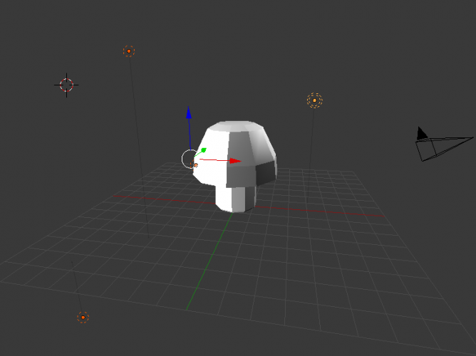
Note that some of your mushroom’s faces are black. That’s going to make it hard to see the colors as you apply them. The contrast is so severe because there is only one light in the default Blender scene. You need to place more lights around your mushroom so that you can see it better.
Hit Tab to go back to Object Mode; lamps can only be added in Object Mode.
Deselect your mushroom with the A key. Move your 3D cursor to the area shown below where you are going to place your light:

Press Shift-A, and choose Lamp > Point. A new light will be placed at the location of your 3D cursor. If you don’t like where the lamp is placed, use the red, green, and blue transform arrows on the light to move the lamp around. You can see how the mushroom gets lighter on the faces toward the lamp, as shown below

If you move your view around, you’ll see that there’s still a problem area — the dark side of the mushroom. (Now THAT would have been a great name for a Pink Floyd album! :]) It generally takes three or four lamps to light a scene well enough to see all the way around an object.
Place your 3D cursor in the general area behind your mushroom, and place a new lamp in that area by using Shift-A, then selecting Lamp > Point. Move the lamp so that it lights up the back of the mushroom. Now, add a fourth lamp below the mushroom so that the bottom is lit up. Tweak the position of all four lamps so that the majority of the faces of the mushroom are no longer black.
Below you can see all four lamps placed in our sample scene, and well-lit the mushroom is on all sides:
Now you’ll be able to see what you’re painting!
Select your mushroom again with the right mouse button and press Tab to switch to Edit mode. Press A to select all, and you will see your UV show up on the UV Editor.
Click the New button at the bottom of the UV Editor to add a new image behind the meshes. Name the image “mushroom”, and click on the Color swatch. Set the color parameters to Red=1.0, Green=0, Blue=0, and Alpha=1, as shown below:

Click OK to save your color setting.
Wow – that’s a lot of red! Zoom out if you need to – this is what you should see:

Save the image by choosing Image > Save As Image from the bottom toolbar. Save it in the same folder as your Blender mushroom file, for convenience, and name this image mushroom as shown below:

You’ve got the red for the top of the mushroom – now you need to paint the other colors on to the mushroom.
In your 3D view, go down to the Mode button (where it says Edit Mode) and choose Texture Paint mode, as so:

On the left, you’ll see your brush options. Move the cursor over your mushroom, and you will see a white circle around it. This is the size of your brush. Click once on the mushroom; you should get a white blurry dot as below:

Hmm — mushrooms usually have big white spots. This isn’t what you want, so undo your brushstroke with Command-Z. Go to the brush options panel, and scroll down the panel to find Curve. Click the arrow next to Curve to expand its options, as so:

Curve defines how color is transferred with your brush. Currently, you have a curve that gives your brushstrokes a soft edge, as the opacity decreases gradually toward the outside of the brush. You want a nice crisp edge on your circles – no dropoff in opacity – so choose the icon on the bottom right to set a constant opacity:

Change the Strengthto 1.0, like so:

Now click on the mushroom head to paint another dot. As a tip, always try to view the area you are painting straight-on, rather than tilted away from you, so that the paint goes exactly where you want it rather than being stretched. You should see the following result:

Yay, a dot! Notice that your dot also shows up on your UV image in the UV Editor.
This is a nice start, but you want the dot to be a little larger. Undo using Command-Z, and change the brush radius to about 45. You can either type in the value, or scrub with the mouse to change the number.
You can also mouse over to the mushroom (so that your cursor shows the brush size), press F, then drag the circle size in or out. Click the left mouse button to accept the new brush size.
Once more, click on the face of the mushroom to paint a dot:

That’s better!
Now move your view around so you can see another face of the mushroom: click and drag your view with the middle mouse button until you have the view positioned as you wish.
If you zoom in and out, you will see that your brush size does not change. This means that if you zoom in and paint a dot on the mushroom, your white dot will be smaller than the previous one. If you zoom in, be sure to increase your brush size accordingly!
Paint another dot on the mushroom. You’ll notice that when the brush overlaps another plane tilted away from the view, the brushstroke will be distorted somewhat, as illustrated below:

If you don’t like the result of your brushstroke, simply undo and try again. Continue placing dots around the top of the mushroom as so:

Don’t worry about getting white on the stalk of the mushroom – you’ll be coloring the stalk later.
Once you are done painting the mushroom top, go to the UV Editor to paint the stalk by selecting the Paint view as shown below:

Change the brush color to a light tan color, like so:

Increase the size of the brush by pressing F and dragging the brush circle bigger with the left mouse button, as so:

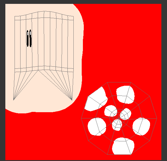
Now paint over the island that is the stalk of the mushroom. It will update as well in your 3D view, as shown below:

Finally, you need to paint the eyes on the mushroom. It would be easiest to paint them directly onto the mushroom, so return to the 3D view. Zoom in and decrease the brush size using F and drag the circle smaller with the left mouse button. Finally, change the brush color to black.
That’s it — you can paint the eyes onto one of the faces of the stalk, as shown below:

Now zoom in and change the brush color to white. Paint two white dots in the upper right of each eye, as so:

Ta –da! You’ve now created your own Mario-style mushroom! Your entire mushroom should look like the following:

Here’s what your texture image should look like:
The last thing you need to do is export your masterpiece so you can use it in your game.
Exporting Files
You will need the following files for use in your projects:
- The
.objfile for the object data. - The
.matfile for the material information. - The
.pngor.jpgfor the texture.
Before you export, make sure everything is named the way you want it – it helps to name everything the same, as you’ve done in this tutorial. Be sure to check that the Material, Image, and Object have all been named the same.
The only thing you haven’t renamed yet is your Object, so head over to the Outliner panel and double-click “Cylinder” to rename it. Call it “mushroom” and hit Enter.
Check your material: it should already be set to “mushroom”, as so:

As well, navigate to the Material tab and check the name, like so:

Okay, looks good! Save your image again to make sure it is up to date.
Go over to the UV editor, click on Image, and choose Save As Image. Give it a name, and save it as mushroom.
Save your Blender file at this point too.
You’re now ready to export! Go to File > Export, and choose Wavefront (.obj) This will save both the object and material files. Name the file “mushroom“.
Ensure that Include Normals and Triangulate Faces are checked under Export OBJ. Change the Forward option to Y Forward and the Up option to Z Up, as shown below:

This is required because in the 3D-view you will be using in your game, the positive Y direction is like looking “forward”, and the positive Z direction is like looking straight up into the sky.
Click Export OBJ.
Congratulations — you have created a cute creature entirely from scratch, and exported the files so that you can use them in your game! You can use this same process to make many simple characters and objects.
You can get the completed Blender files here, if you would like to compare them to your own files, or just to see what the finished files look like.
So guys ur Mushroom is ready........
so here is the pic of ur mushroom....

Superb tutorial 😀
ReplyDeletethanks buddy!!
Delete