 In the Previous Blender Tutorial, you created a happy little mushroom, who is quite the “fun guy”. However, a static mushroom in your game won’t be terribly exciting; the mushroom should hop and nod as he moves around the game scene.
Fortunately, Blender can help with this task. In this tutorial, you’ll learn how to render out a series of images you can use in a sprite sheet to animate your mushroom.
Let’s get hopping
Getting Started
For this tutorial, you can either start with the mushroom you created in the previous tutorial, or if you’d rather get right into things, you can download the starter project here. Either way, there are a few steps you need to complete before you can animate your mushroom.
Even though you can see everything clearly in Blender, if you rendered the 3D scene to a 2D image right now, you wouldn’t see anything in the images!
This is because in the previous tutorial, you created a texture within blender, but you never formally associated it with the mushroom object’s material. This is required so that Blender knows to apply the texture to the object when rendering. You’ll do this now.
Adding a Texture
In the Properties window, left-click the Texture Context button — it looks a little like a checkerboard, as shown below:

Note: In the Blender documentation, you’ll see the acronyms of LMB for left mouse button, RMB for right mouse button, and MMB for middle mouse button. Take this as a heads-up for when you dive into the Blender documentation!
Add a new texture by clicking the New button (no surprises there), like so:

A name field and drop down list for the type of text appears; change the default Type from Clouds to Image or Movie. In the Image panel, click the drop-down to the left of the New button and select either the mushroom image you made in the previous tutorial or mushroom 3.24.53.png if you are using the starter file for this article

In the Mapping panel, select UV for Coordinates, as such:

Okay — that’s all the tweaks you need to make to the original file. It’s a good idea to save your changes as you move through the tutorial.
In order to animate this character, you’ll need to add an armature.
Armatures for Amateurs
An armature in a 3D program works much like a skeleton. Just as your muscles move with your skeleton, the mushroom’s mesh will move with its armature. In Blender, the armature is simply another type of object; you’ve already worked with mesh objects. The armature object comes with one bone in it by default.
Adding Rigging, Bones and Skinning
First, you’ll need to cover a few bits of terminology. The process of building the skeleton is called rigging. You’ll first create an armature with one bone, then you’ll add an additional bone; this will be your rig.
Rigs can get very complicated, such as when you’re constructing a 3D human character. There are constraints and modifiers that can be added to your rig to simplify the animator’s job when working with complex rigs. Your mushroom’s rig will be simple, but will serve your needs just fine.
Skinning is simply the process of associating the vertices of your mesh with the bones in your armature.
Once you’ve created a model, you animate it with the following steps:
- Add an armature to your scene
- Add some bones to your armature
- Skin the mesh to the bones
- Animate the armature by posing the bones
Adding an Armature
First, press Option-Z to toggle the viewport shading from textured to solid — this way, it will be easier to see the armature. You can also toggle the viewport shading by clicking on the little sphere at the bottom of the 3D view to bring up the Viewport Shading menu and choosing Solid, as so:

Your mushroom will now appear white rather than your beautiful mario-style white and red.
Move your mouse over the 3D View and press Shift-A. Select Armature -> Single Bone. from the Add menu, as illustrated below:

Note: The reason you need to have your mouse over the 3D view is that many of Blender’s keyboard shortcuts are context sensitive based in which window or editor the mouse currently rests
The Object Data Context
In the Properties window, click on the Object Data context button that looks like a stick figure, and ensure Names and X-Ray in the Display panel are checked.
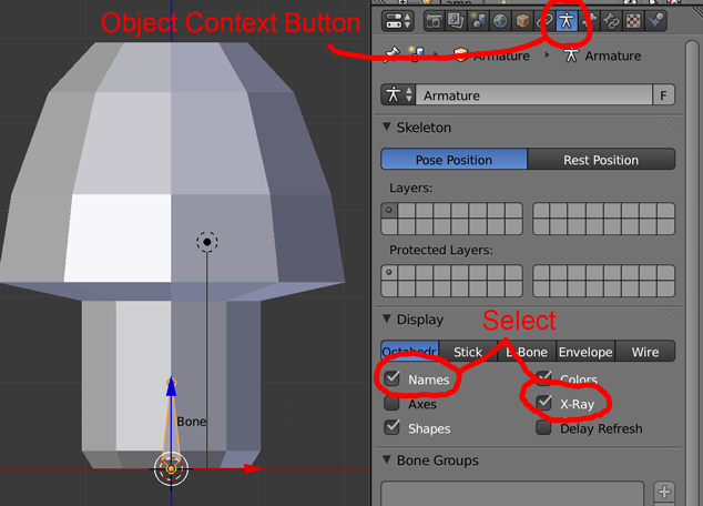
The Names option shows the names of the bones in your 3D View, while X-Ray ensures the armature remains visible even when objects are in front of it.
The context button in your case represents the armature’s object context. If your mushroom was the active object instead, then this button would be displayed as a mesh. Since an armature is currently the active object, the icon reflects the armature context.
In the Properties window, the buttons relate to different contexts; for example, the Render context, or the Scene context. The number of buttons in the Properties window changes based on which object you select in the scene, as shown in the image below:

Additionally, some of the buttons even change images; the Object Data context button changes from a stick figure to a mesh to a movie camera, depending on what is currently selected.
The tooltip of the button says “Object data” which makes sense: if you have an armature object selected, then the data corresponding to that object is an armature in the current context — hence “object data context”.
Entering Edit Mode
Move your back over the 3D View and press Tab to switch to Edit Mode for your armature.
Take a look at your armature: every bone in your armature is made up of three parts: the root, body, and tip, as shown below:

Right-click on the tip of your bone, press G to grab it, then type Z to restrict its movement to the Z axis. Move the tip of the bone to the top of the mushroom’s stalk, as shown below:

Left-click to confirm your action. This bone will be the one associated with moving the vertices of the stalk.
Extruding Your Armature
Just as you did to extrudes faces on a mesh in the previous tutorial, choose Extrude from the menu to the left of the 3D view (under Armature Tools), or alternatively press E to extrude from the tip of this bone. Next, press Z to constrain movement to the Z axis, and drag the new bone to the top of the mushroom’s cap, as such:

All bones must be uniquely named, so Blender automatically gives the new bone a unique name by appending a number to it. This bone will be the one associated with moving the vertices of the mushroom’s cap. You now have a skeleton for your mushroom.
Working in the Bones Context
The ominous sounding and looking Bone context button has a bone on it; it’s only available when the active object is an armature object. Left-click on the Bones context button to view the panels related to bones, as indicated below:
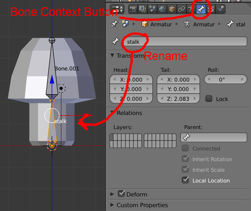
Right-click the bone named Bone in your 3D View. In the field at the top of the Bones context, rename this bone to stalk.
Now select the bone named Bone.001 in the 3D View and rename it cap.
Parenting the Mushroom to the Armature
Now you’ll create a relationship between the mesh object and the armature. Press Tab to exit Edit mode. Press Z to view your scene as wireframe, or alternately choose Wireframe from the Viewport Shading menu.
Right-click on the mushroom, then Shift-right-click on the armature. This selects both the mushroom and the armature, and sets the armature as the active object.
Note: In Blender you can have any number of selected objects, but only one of those can be the active object. The most recently selected object is the active one; it’s highlighted in bright orange to indicate this fact. Switching your view to wireframe makes it easier to see which object is active.
Skinning Your Bones
Another macabre sounding subject — skinning — is the process of associating the vertices with the bones. Fortunately, it’s fairly easy for you to do this with your mushroom.
Press Control-P to show the Set Parent To menu. Select With Automatic Weights under Armature Deform, as shown below:

This step parents the the mesh to the armature and sets the weight attribute — or the amount of influence that a bone has over a vertex — to “automatic”. This means that Blender will take a guess on the influence based on the proximity of the bones; it usually does a pretty good job.
Working in Pose Mode
Right-click the armature, then press Control-Tab to enter Pose mode; alternatively, you can select Pose Mode from the Mode menu. Note that selected bone turns cyan, as shown in the screenshot below:
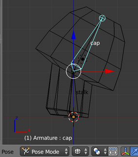
Right-click the cap bone, press R and move your mouse to rotate the bone. Note that the cap moves with the bone. By moving the bones, you can evaluate how well the automatic weighting work. It worked pretty good, but the base of the stalk is lifting a little. Since this is RayWenderlich.com, you’re going to take things a little further!
Working with Vertex Groups
So far, you have let Blender automatically associate which vertices are tied to which bone. However, it’s important to understand how you can do this manually if you want more fine-grained control. Note that this section is optional (since you’re simply doing what you’ve already done in an alternative way), so if you don’t care about this and want to get on with the animation, feel free to skip to the next section.
First, right-click to discard the rotation action. Next, right-click your mushroom and press Tab to enter Edit mode. Left-click the Object Data context button; you’ll note that it looks like a mesh triangle in your new context.
Look at the Vertex Groups panel; you may need to expand this section if it’s not visible. Your panel should look like the screenshot below:
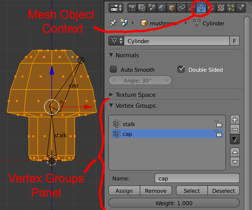
You’ll see two vertex groups that have the same names as the bones in the armature. That’s because bones are mapped to vertex groups by their names.
Note: You can create named groups of vertices in Blender. A vertex can also belong to more than one group: the loyalty of that vertex to the group is based on its Weight value (from 0.0 to 1.0).
You’re going to remove the vertices from the existing groups and explicitly add them back. It’s possible to create named groups first and then add the vertices later, but then you wouldn’t have had the option to skip this section.
Leave all of the faces of your mushroom selected, left-click ‘stalk’ in the list, then left-click on the Remove button. Repeat this action for ‘cap’. Move your mouse over the 3D view and press A to deselect all.
Press B and select the vertices that belong to the stalk of the mushroom by dragging a box around them. In the Vertex Groups panel, select the ‘stalk’ group and click the Assign button, as so:

Now click Deselect.
Next, select the vertices of the cap (again using B to drag a box around them), select the ‘cap’ group, and click the Assign button.
You can use these groups to easily select specific groups of vertices — and more importantly, Blender knows exactly which vertices are moved by which bones.
Creating the Hop
Now that you’ve laid the framework for your mushroom to move, you can now add some animation to your object. You want your mushroom to squash and stretch while it hops; you create this effect by squishing the mushroom, stretching it as it hops into the air and squishing it again on landing.
In Blender, you perform animations by creating a series of keyframes. In each keyframe, you put the object in a different pose, and Blender will smoothly interpolate the movement between keyframes.
Note that when you create a keyframe, you need to specify the type of the keyframe – i.e. are you modifying the location, rotation, or scale of the object. Let’s take a look at how this works in practice now.
Working in Pose Mode
Press Tab to enter Object mode. Right-click on the armature; you should already be in Pose mode, but if not, press Control-Tab to enter that mode.
Select all the bones by pressing A until they are all selected.
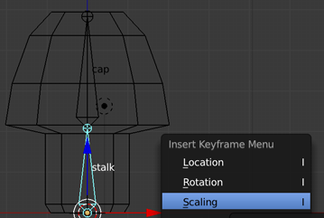
Right-click the stalk bone, and press I to view the Insert Keyframe Menu. Select Scaling.
The Timeline Window
The Timeline window appears at the bottom of your screen; it looks like the following image:
After you insert a keyframe, you’ll see a vertical yellow line appear in the green line. The green line indicates which frame you’re on.
Keyframing the Hop
Move the mouse over the Timeline window and press the Right-Arrow key three times to advance to frame 4. Leave the stalk bone selected, press S to scale and then press Z to restrict scaling to the Z axis. Move the mouse to squish that shroom, and left-click to accept the scaling. The screenshot below shows you about how much you should squish the mushroom.

Notice that the cap of the mushroom squishes as well; that’s because the cap bone is a child of the stalk bone. Type I and select Scaling from the Insert Keyframe Menu.
Advance to frame 8 using the right-arrow key and type Option-S to clear the scaling. Next, type I and select LocScale to set a keyframe for both location and scaling.
Note: You will see many options in the Insert Keyframe Menu, but typically you want to set keys for just what is necessary. In the case of the the mushroom, we didn’t need to set the location and the scale initially because we weren’t going to be changing the location yet.
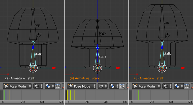
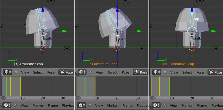
Left-click and drag on the Timeline window to scrub between the keyframes to see the transformation. Notice the text at the lower left of the 3D View is orange for frames that have keyframes and white for ones with no keyframe. The screenshot below shows what you may see at various keyframes as you scrub.
Go to frame 14, move the mushroom up in the air by typing G, then Z, and left-click to confirm when you like the height. Type I to insert a keyframe and select Location.
Advance another two frames and insert another keyframe for Location on frame 16, so your mushroom hangs like Michael Jordan at the top of its jump.
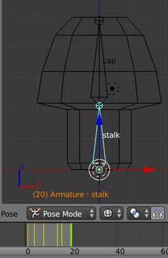
Finally, go to frame 20, type Option-G to clear the location, type I and set another Location keyframe.
Previewing the Animation
Move your mouse to the Timeline window and left-click on the last keyframe. Press E to set the end of the frame range; the lighter section of the timeline should change from extending to the right of the timeline window to being constrained between your keyframes, as you can see in the screenshot below.
It’s time for the big reveal! Press Option-A to see the mushroom animate in real-time. Press Escape when you’re done marveling at the life you’ve brought to the mushroom. Now you know why your mushroom is such a fun guy — because he’s so hoppy! (Okay… okay… I know that’s bad, but I’m lichen that pun quite a bit.) :]
Working With the Animation Screen
So far, you’ve done all your work in the Default screen layout, using only the Timeline to see keyframes. However, Blender comes with many handy screen layouts to make your life a little easier.
The Animation layout is a great example. Left-click the button next to the name of the screen layout and select Animation, as shown below:
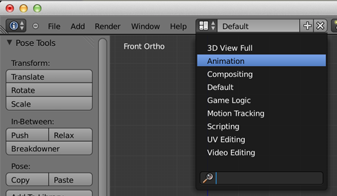
In this layout, you’ll see a set of windows that relate to typical animation tasks. Notice the 3D View has changed: the mushroom is now in solid shading mode again and you’re viewing it in perspective, as shown below:

Dope Sheet Window
In the Dope Sheet window you are initially looking at the Dope Sheet mode: if you had multiple objects animating, they’d all be listed here. Where you could only see the keyframes of the selected object on the Timeline, here you can see it all.
Note: The term “dope sheet” comes from traditional animation where it is also known as an exposure sheet. Similar to traditional animation, Blender’s dope sheet gives the animator an overview of all the actions occurring in the timeline.
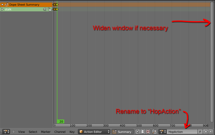
In the Dope Sheet window, change the mode to the Action Editor, like so:

Now you’ll see just the Action that you’ve created for the mushroom and its keyframes. It has the default name of ArmatureAction, so rename the action to HopAction in the name field, indicated below:
If you want to zoom in on the keyframes so they don’t looks so squished together, you can use same commands you use in the 3D View for zooming: mouse wheel in or use Control-Middle-Mouse button. The point it scales from is the green line.
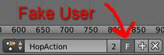
Creating a Fake User
Elements in a Blender file that are no longer referenced will have zero users. When you quit Blender and come back to it, those elements are not longer there. By creating a fake user, you keep Blender from trashing an unreferenced element that you might want to use later.
To the right of the name field is a button with an F on it; left-click it to create a fake user for this action.
Disconnecting the Hop Action
Next you need to disconnect the hop action so that you can create a second animation. If you didn’t do this, you’d be building on top of the hop animation (making it nod while it hopped), and that’s not what you want in this case.
Left-click the X the right of the F and +. This disconnects this action from the armature. The armature is no longer being used by the mushroom, but fortunately it now has a fake user to keep it from being discarded upon exit.
That takes care of the bounce — now you need to create another action to handle the nod.
Creating the Nod
First, you need to ensure you’re at frame 1 of the animation Move the mouse over the Timeline or the 3D View windows and press Shift-Control-Down Arrow to move to the first frame.
Select View > Right in the 3D View header, then select View > Persp/Ortho to see your mushroom in the orthagonal view, like so:
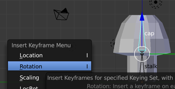
Right-click to select the cap bone, then press I and select Rotation.

Move to frame 5. Press R to rotate the mushroom to the left, then press I to keyframe the rotation.
Advance to frame 10, press Option-R to clear the rotation, then press I to key the rotation change.
Scrub through the Timeline or Action window, and you’ll see your mushroom nod.
Click on the last frame in the Timeline and type E to set the end of the animation. Ready to see your work? Press Option-A to see a preview of your active mushroom.
In the Action editor of the Dope Sheet window, name this action NodAction, then click the F to make a fake user, as shown below:

Making Sprites
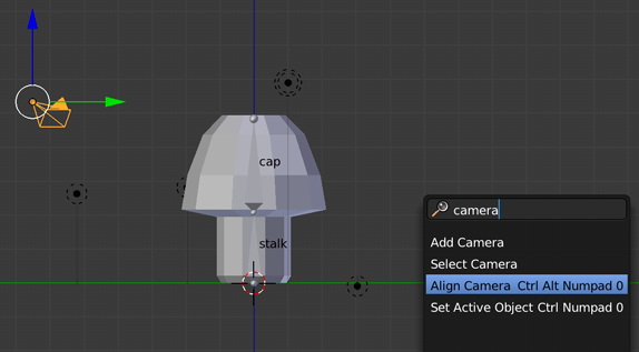
Now you need to move the camera so it is looking from the same point-of-view as the Right Ortho view. Fortunately Blender has an easy way to do this. Right-click the camera to select it. Press the spacebar, type camera and select Align Camera Ctrl Alt Numpad 0, like so:
Click on the first camera icon in the Properties window, the one that looks like a 35mm camera. This is the Render context button. The Dimensions panel is where you set the resolution to the size of the sprite you want to make. For this tutorial, imagine you want a sized 128×128 pixels. Set to X: 128, Y: 128, and 100%. Set the End Frame to 20, like so:

Press Option-Z to toggle Texture shading on again.
In the Properties window, click on the camera icon that looks like an old movie camera. You should be familiar with this button — it’s your old friend, the Object data context again. Make sure you have the Camera selected: left-click Camera in the Outliner panel if necessary.
Left-click Orthographic on the Lens panel and enter 8 into the Orthographic Scale field so that the mushroom animation fits within the bounds of the camera.

Position the camera so that the mushroom is centered in the viewport using the G key.
Now you need to assign the HopAction to your object. Right-click on the stalk bone, then navigate to the DopeSheet Action Editor and choose HopAction from the dropdown menu, as shown:

In the Shading panel of the Render context (the first one on the left that looks like a camera), set the Alpha to Transparent.

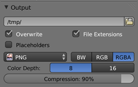
In the Output panel further down in the Render context, select the output folder for your rendered files and left-click the RGBA button, as so:
Note: By default, Blender names the render files as 0001.png, 0002.png, and so on. However, you have the option to add a name to the numbered files so that you can tell what they contain at a glance.
If you append “hop” to the path the files will be named as hop0001.png, hop002.png, and so forth. Furthermore, since you know you will have fewer than a hundred images, you can append “hop##” to the path and your output will be hop01.png, hop02.png, etc.
Click Animation at the top of the Render context in the Render panel. Blender will render your animation frames to individual files and save them to the folder you specified above. To view the fully rendered animation, click the Play button; if you don’t see the playback window immediately it may have popped up behind the main Blender window. If so, just press Command-Tab to find the playback window.
If you want to take a look at our version of the finished project, you can download it here.
If you have any question or comments, we’d love to hear about it in the forum comments!
Thanks for reading...!!!
No comments:
Post a Comment